


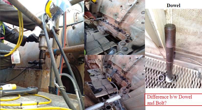
- Bolts of gas turbine Compressor and casings are classified as Horizontal and Vertical Bolts. Horizontal bolts are fastened at horizontal axis where vertical are radial ones.
- 2 Dowels are fastened at either sides of each casing. Remaining are the bolts, fastened with nuts.
- Dowels are removed first than the remaining bolts. Methods for unbolting the casing bolts are:
- Heating and Hammering (Heated until the bolt becomes red hot)
- Pressure Source
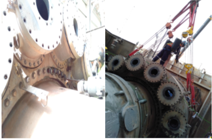
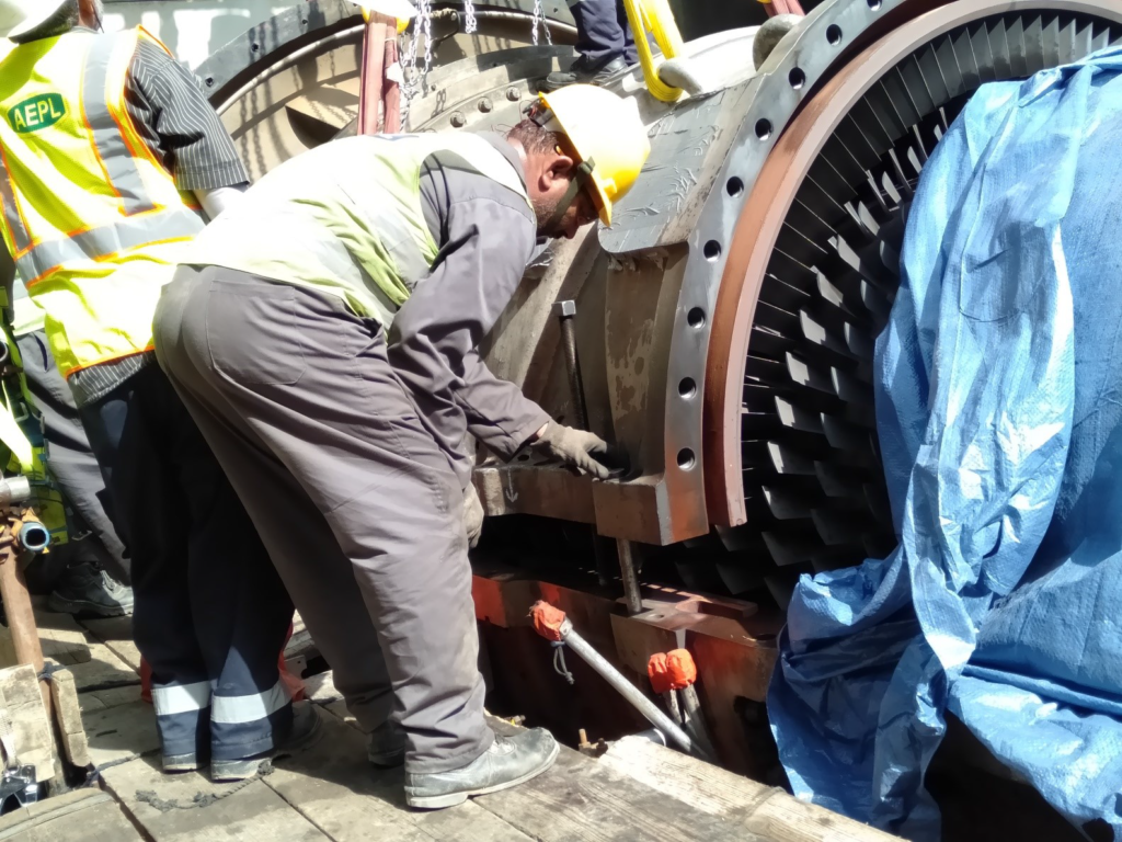
Uplifting of Casing Upper Halves
- Jacking Bolts are used for splitting the casings. Jacking bolts are torqued; they are accessed through their provisions from upper half casing to the lower casing surface.
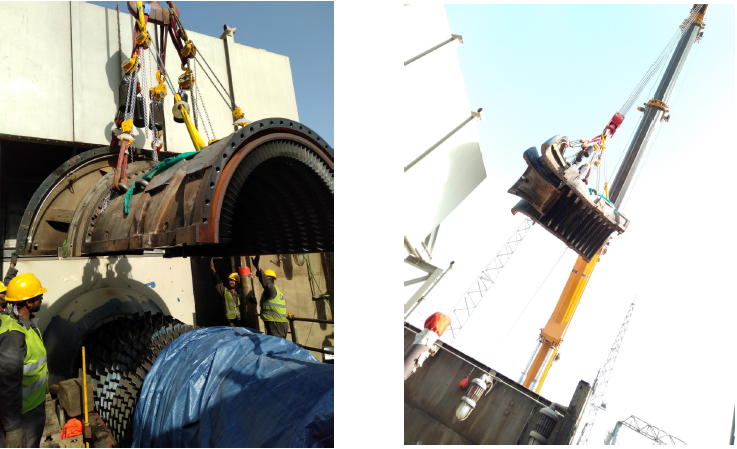
- The Crane radius and boom length should be under consideration, while lifting; a proper Lifting Procedure should be given for each casing and rotor.
- When the casing split up, the upward travelling is constantly monitored by metering. That assures the uniform travelling of the casing half from both sides.
- In case of Compressor and turbine upper halves, jacking is done until the blades of stator and rotor are freed.
- The crane boom remains on load during the jacking, and boom goes up if the upper half is freed from the lower one.
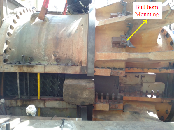
- Guide pins, one each side of the casing, are installed into the bolt access holes for consolidating the concentricity of the casing’s halves.
- Weight is also an other important factor to consider while lifting; if it goes beyond limit, should the casing be hinged. That’s why the weight should be noticed consistently while booming up the casing.
Combustion Wrapper Casing Uplifting
- Lines, tapped from the combustion wrapper, should be removed, before lifting the wrapper casing.
- One bolt of all can covers, opposite to the can cover joint, should be engaged, while lifting.
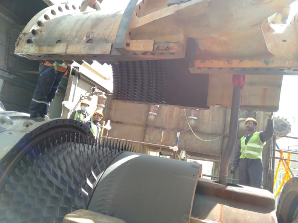
Compressor Section
- Gas Turbine Compressor section is composed of four horizontal split casings. They are: inlet casing, forward casing, after casing and compressor discharge casing.
- Lines (upper half), cooling and sealing lines (5th stage extraction), surge control lines (11th stage extraction), associated with the compressor section; should be removed for casings dis-assembly. The manifolds: Atomizing air, Purge air and Gas Fuel; upper halves should also be removed.
- First, the CDC (compressor discharge casing) is removed, forward and after casings are removed together afterwards, and may or not be the Bell-mouth attached with. For removing the Bell-mouth, its housing should be removed first. The sequence of removing the casings may vary as per TA command.
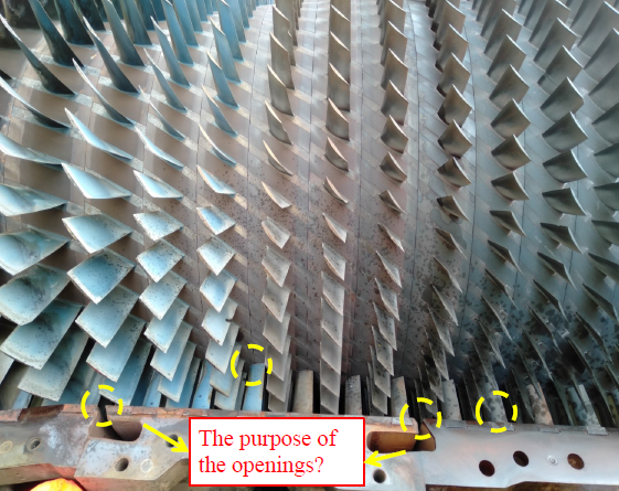
6 Points Check
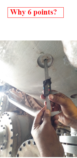
- 6 points check are recorded before compressor casing upper halves removal. 16 access holes are located on gas turbine compressor casings, 4 at each top and bottom, and 4 at each left and right. Where, 8 access holes are located at turbine, in the same manner as the compressor.
- These holes are covered with the locking plugs. From these holes, the vernier depth is accessed. The vernier depth goes deep and touches the blade tip, total reading of vernier is than subtracted from the casing thickness, which is punched on the casing. Turning of the rotor may needed, if any rotor blade doesn’t exist at the location to the access hole. For turning, ROSH Permit is required.
- The plugs are located on compressor rotor wheels: 1st, 7th, 13th and 17th. Whereas, in the turbine case, on turbine 2nd and 3rd wheel.
Compressor Discharge Casing (CDC)
Bellmouth + Forward + After Compressor Casings
Compressor Clearances
The radial clearances are measured between, rotor blades and casing, and casing blades and rotor surface, at the horizontal axis.
The readings are recorded, from left and right sides, at each compressor stage composed of one stationary and rotary blade. Feeler gauge is used for measuring.


