

Inspection
In engineering activities inspection involves the measurements, tests and gauges applied to certain characteristics in regard to an object or activity. we will briefly explain how to do Gas Turbine services and Major Inspection.
WHY? Inspection helps to control; quality, reduces downtime costs, eliminate scrap losses and assignable causes of defective work.
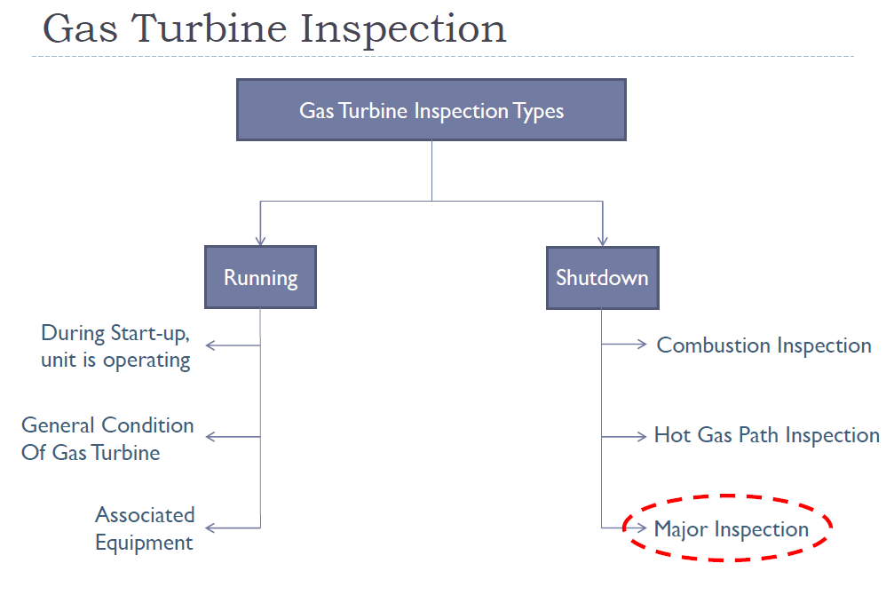
Major Inspection
It involves the inspection of all major flange to flange components of Gas Turbine services, which are subject to wear during normal operation.
- It includes:
- Combustion Inspection
- Hot Gas Path Inspection
- Inspection of casings (Cracks, Erosion)
- Rotor and Stater blades of Compressors (Tip Clearances, Rubs, Bowing, Cracks)
- Compressor air inlet housing (Fouling, Erosion, Corrosion, Leakage)
- Bearings and Seals (Measurements against Original Values)
When? Based on 64000 Running Hours or 2400 Starts.
Pre-checks
Pre-checks are measured for determining the pattern of the machine before dismantling.
Following are the Pre-checks;
- Load Coupling to Generator Alignment check
- Bump Test
- Set Back measurement
- Compressor Clearances
- A-set readings
- Turbine Clearances
- Bearing Clearances and its labyrinths
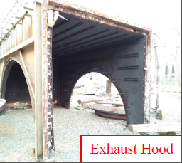
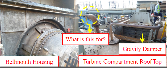
Roof and Walls Removal
- The activity is performed for facilitating the Gas Turbine casings and parts to lift up by means of crane.
- The roof and walls of turbine and Load Coupling compartments are removed.
- The processes involved in removing the roof and walls are: Cutting, Grinding and Unbolting.
- All of the Flex seals are taken out for the replacement.
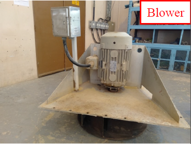
- All of the dampers and blowers are removed prior to roof lifting from the Turbine and Load Compartment roofs.
Combustion Section
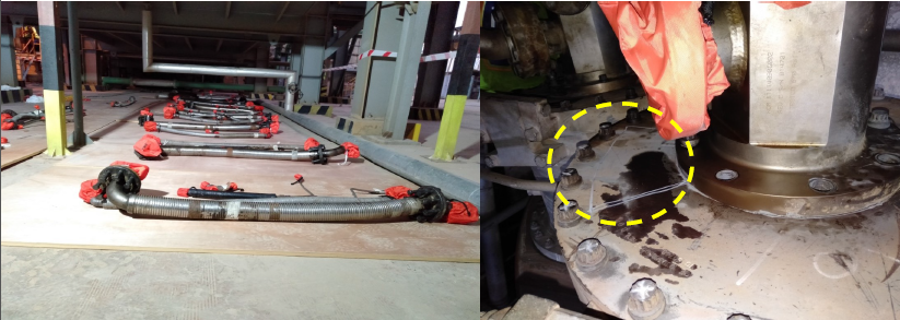
The MI starts with the combustion section. All the tubing and piping are first subjected to remove, which are flanged to flanged with the nozzle assembly; tapped from the respective manifolds: Atomizing Air manifold, Purge Air manifold, Fuel Gas manifold and Liquid Fuel lines.
CI Hardware Dismantling Order:
The dismantling of the combustion section is subjected to the steps followed;
- Fuel Nozzle assembly removal
- Spark plugs and Flame Detectors Removal
- Can cover opening and Crossfire Retainers removal
- Crossfire tube removal
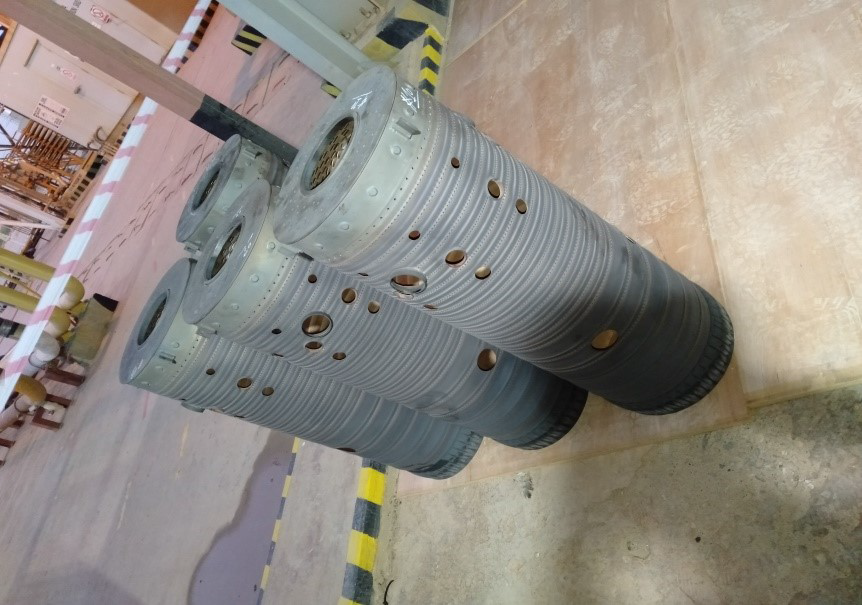
- Liner Extraction
- Flow-sleeve removal
- Cans removal 5 & 11
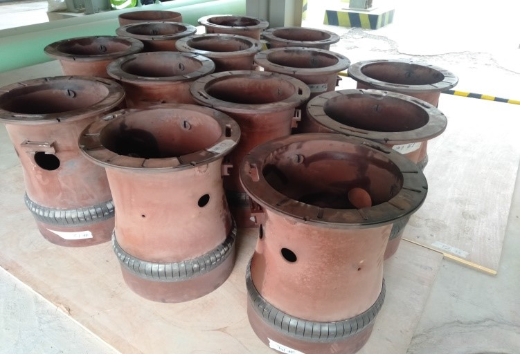
- Transition Piece Removal
CI Hardware Removal
When all the lines are removed, associated with the nozzle assembly; the nozzle assembly is unbolted. It is hanged with the crane boom by means of chain block, lifted up as recessed from bolts.
What does the white mark on can cover indicate?
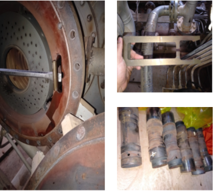
- Can cover, when unbolted, crossfire tube retainers are subjected to remove. Two retainers are associated with each can. Crossfire tubes are in male and female part, the assembly pushed in the crossfire tube cover to make free the liner and flow sleeve. The retainers are removed by inserting a screw driver/ crowbar’s flat head into the retainer and pulling it outside the flow sleeve.
- Liner is stuck by Hola seal at aft end into the Transition Piece, and from the fwd end, supported by three lugs into the flow sleeve grooves. It is extracted by pushing the liner outside from the sleeve.
Hola Seal Flow sleeve is bolted with the combustion can face flange by means of 4 allen key head bolts. When unbolted, it is extracted by a lever hoist. The hook is arranged into the holes configured into the flow sleeve, and pulled out.
What is the indication?
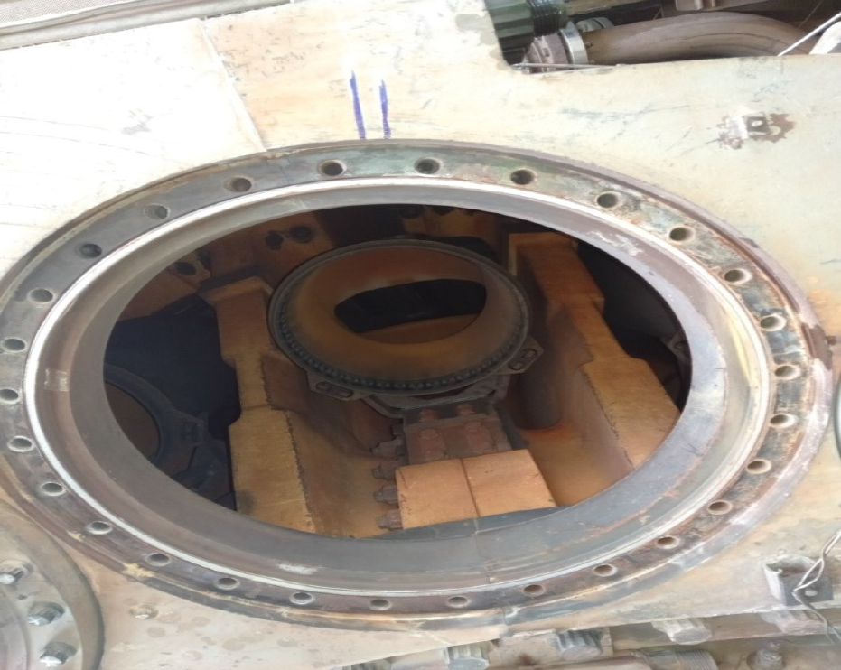
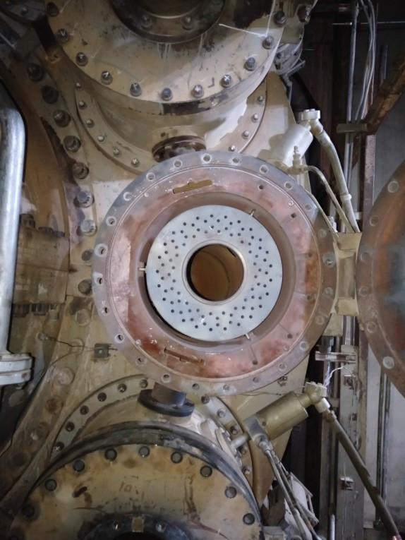
Cans 5&11 are removed, for getting into the wrapper, for unbolting the transition pieces. The cans, aforementioned, are also exist at the horizontal joint of combustion wrapper casing.
Set Back Measurement
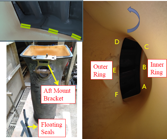
- Transition Piece is engaged with floating seals from fwd end into the 1st stage nozzle outer and inner ring groove.
- Side seals are used for sealing the transition pieces from sides.
- The fwd face of transition piece has the ways for introducing the seals.
- The measurement is taken by vernier caliper for measuring the inner distance between the collar of the transition face and 1st stage nozzle ring collar.
- Range: 250±50 thou
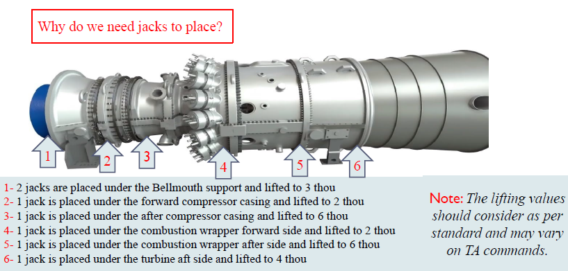
Jacks Placement
Mechanical jacks are placed before unbolting the upper half casings. These jacks are lifted to metered value after appointing at the lower half casings.