


- All the radial and horizontal bolts, of the turbine upper half, are removed.
- The first stage nozzle ring locking pin is removed prior lifting the turbine shell.
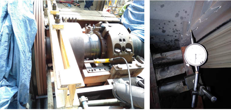
Bump Test
- Bump test is performed for checking out the maximum displacement/float of the compressor by keeping the rotor on bearings. The jacking can be done either from fwd or aft side of the compressor rotor.
- 2 hydraulic jacks are used to push the rotor uniformly, placed on horizontal axis on rotor wheel face. Packing is introduced for making the require length of hydraulic jack, If require.
- A dial gauge is introduced with the magnet fixture, mounted on the solid surface free from the rotor, for checking out the maximum displacement indication Bump test.
- As, the jacks push the rotor, the rotor will be displaced as per allowable limit provided by the thrust housing.
- The limits range between 13 to 17 thou, if the brush seal exists in the pressure packing. Rather than that, the range falls between 21 to 27 thou.
A-set Reading
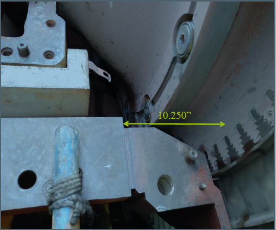
- The reading is measured between the CDC outer cylinder aft surface and first stage rotor wheel of turbine, from both sides, left and right.. A-set reading, if disturbed, will affect the turbine clearances.
- For recording the reading, the rotor should be displaced at active side thrust bearing. The nominal reading is the 10.250”, measured by the Inside Micrometer.
Turbine Clearances
- Turbine clearances are radial and the axial ones. They are recorded by Feeler gauge, Telescopic gauge and vernier calliper.
- The clearances, close to the reference values, will increase the unit performance.
- They are recorder when the rotor is at active thrust bearing side.
- The clearances are categorized as fwd and aft sides clearances, and recorded between, the buckets and shrouds, and the diaphragms and rotor land.
- Shrouds of 2nd and 3rd stage are equipped with the labyrinths and honeycomb seal. Which minimizes the bucket’s tip leakage. Whereas, the 1st stage shrouds are plain and thermal barrier coated.
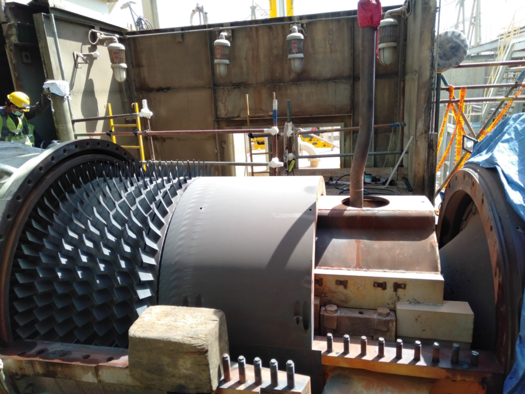
Exhaust Shell Removal
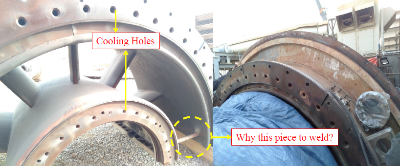
Exhaust shell is connected with the turbine shell and is composed of inner and outer cylinders. The cylinders are separated by radial struts, which have internal cooling passages. Passive cooling air also gets the provision to flow to inner cylinder and to the turbine shell outer cooling. 88tk lines are first removed before uplifting.
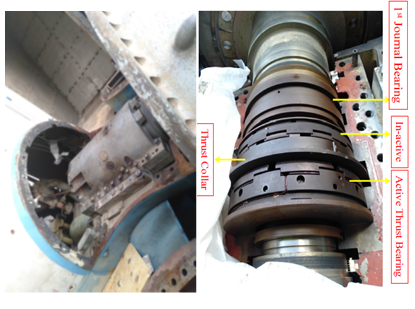
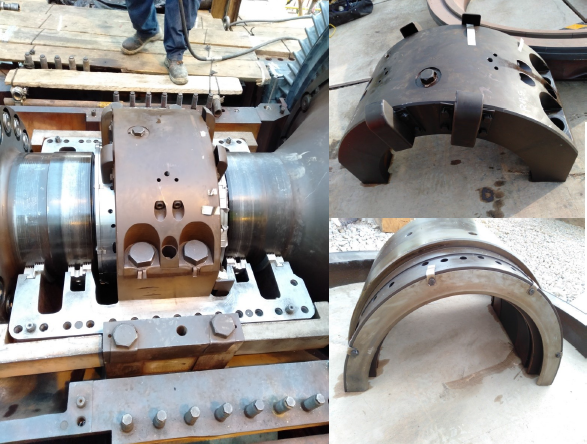
Bearings
- Three Journal bearings are responsible for bearing the radial load of the combined rotor. Whereas, a couple of thrust bearings are compensating the axial thrust of the rotor.
- The journal bearings are in-housed, horizontally split type housings and bearing liners, packed with the labyrinths for sealing. Air is introduced for cooling and sealing purpose.
- For extracting the bearings, their housings are first subjected to remove. Then, the upper bearing liners are removed. Upper labyrinths packing are keyed into the upper housing; whereas, lower ones are freely inserted into the lower housing.
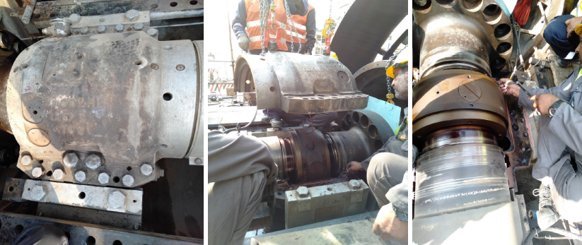
2nd Bearing Housing
- 2nd bearing housing rests inside the CDC inner cylinder. The vent and supply line, for cooling and sealing air, is accessed from the Combustion wrapper.
- The marriage coupling is housed inside the inner barrel. The inner barrel is first removed for recessing the 2nd bearing housing.
- The inner barrel is bolted from four locations, two at either side. Whereas, the pin lock adjacent to the bolt position, gives the provision to the jacking bolt for lifting up the upper half of the inner barrel. Similarly, the bearing housing is unbolted and lifted up by tying eyebolts and shackle.
- The 2nd bearing liner strap and bearing liner upper half are unbolted and lifted up through eyebolts and shackle, by means of crane.
3rd Bearing Housing
3rd bearing is housed inside the exhaust frame inner cylinder. The housing is unbolted and then uplifted through eyebolts and shackle, powered by the crane. 3rd bearing liner, is also bolted through casing bolts to the lower liner, removed when unbolted.


