


- IGVs are segmented, each stem goes independently to the bellmouth IGVs opening hole, where the pinion is attached. The pinion is fastened by means of screw and key. A spring washer is introduced beneath the each pinion.
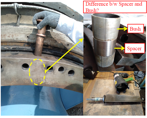
- The IGV stem surrounds by the bush and spacer arrangement, as shown. These bushes are lubricated by greasing.
- A rubber washer is placed at the aft side of the stem.
- The lower part of IGV rests in the segment and surrounds by teflon bush.
- All the IGVs are subjected to FPI test, for checking out any pitting, crack and wearing.
Bearing Clearances
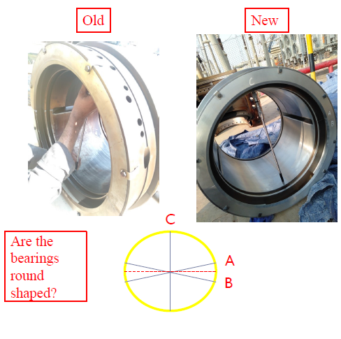
- Bearing clearances are taken of old and new one.
- Methods used are: ID/OD method and Lead Wire method.
- External micrometer for measuring the Journal outer diameter .
- Ranges between 10-15 thou
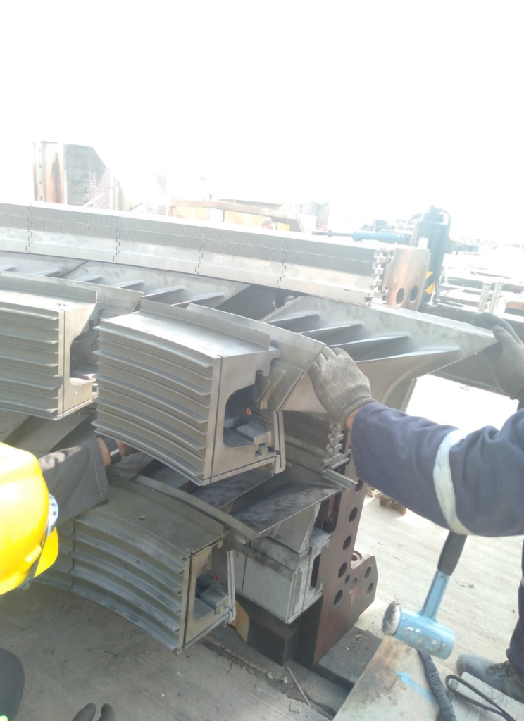
Make-up of the Turbine Shell
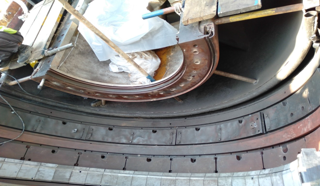
- Turbine lower half is boxed up while kept on turbine base. All the shrouds are first mounted onto the shell. New shrouds are first positioned according to the number and punched from the pinhole, through the shell, for drilling. Where drilling, on the shrouds, is made on site. After shrouds mounting, nozzle segments are installed by sliding, between the shrouds, of two consecutive rows.
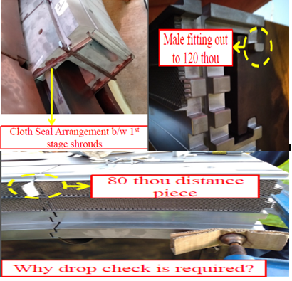
- For drilling, all the shrouds are first installed by number configuration. The first and last shroud in the turbine half shell is clamped by keeping the male fitting out to 120 ± 20 thou and rest of shrouds are arranged by keeping the distance of 60 ± 20 thou, in each. This is known as Drop Check Reading.
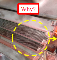
1mm central deep cut into the shrouds honeycomb located at the horizontal joints.
Make-up of the Turbine Rotor
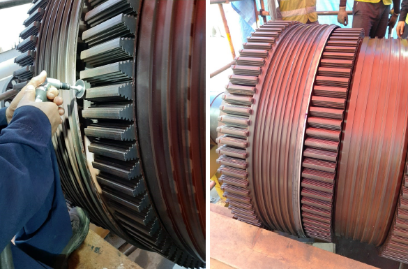
- Repairing of the discourager seal, if found damaged.
- The groove is first cleaned by means of small disc grinder and chiseling. Then a seal, in four pieces, is inserted into the groove.
- The collar of the seal out of the groove and central distance of pieces must be uniform from all the periphery.
- At the end, it is pinched for locking from different locations.
- Cleaning of the dovetails.
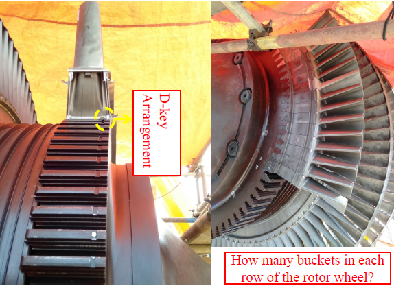
- All the buckets are arranged into the dovetail arrangement.
- After installation, all the buckets are locked.
- The position of the 1st bucket at the 1st rotor wheel can be changed, in parallel to the previous one. For sake of repositioning, a hole for axial pin, is drilled.


