


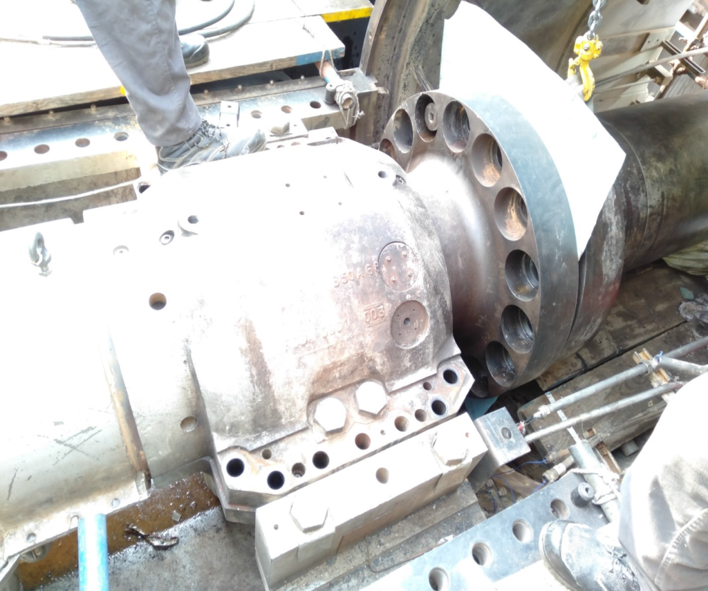
Load Shaft Coupling Disengagement
- The load coupling forward flange should be disengaged prior to the turbine rotor lifting.
- The load shaft should be hanged with the lever hoist and pushed with the jacking bolts towards the Generator end. So that, rabbit of the turbine rotor flange will be free.
- The travelling of the turbine rotor can be resisted while putting hydraulic jacks at first rotor wheel fwd end.
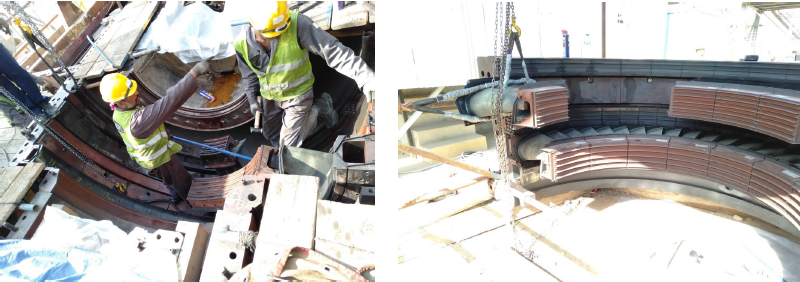
Uplifting of the Turbine Rotor
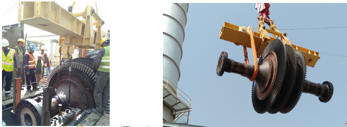
- The lifting of the turbine rotor is identical to the compressor rotor. The turn buckle of the lifting beam is adjustable for maintaining the equilibrium, while lifting. The clearances of the nozzle and buckets are important to be considered.
Lower Bearing Liners Replacement
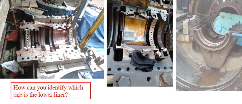
- After lifting the Rotors, all the lower liners of bearings are removed, lower housings are cleaned. Lower housings then equipped with the new labyrinth and the bearing liners.
Turbine Shell Dismantling
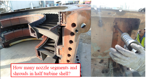
- For dismantling the turbine shell, all the locking bolts are removed.
- All the shrouds and nozzle segments are pinned with the turbine shell. For getting access to the pins, bolts are first removed.
- Pins are internally threaded and removed by a threaded bar, by tying the threads, and pulled it out from the shell.
- The 2nd and 3rd nozzle segments slide into the shrouds. The nozzle segments are integrated with the seals, however, in case of shrouds, seals are inserted on site. Cloth seal for the 1st stage shroud, and for the 2nd and 3rd stage shrouds, key seal is introduced.
Lower half of the turbine shell is dismantled by keep mounted on the turbine. For removing the 1st stage nozzle ring lower half, the locking pin is removed first. The shrouds and segments are removed in the same manner as done in the upper half turbine shell.
Turbine Rotor Dismantling
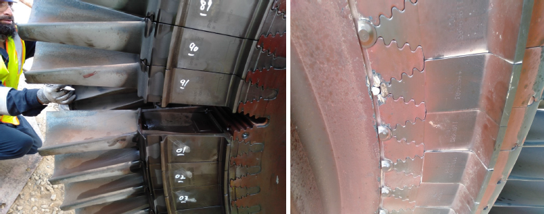
- The turbine rotor buckets are first numbered before removal. The first rotor wheel buckets have the D-key arrangement, whereas, the 1st bucket has the axial and radial pins for locking. The 2nd and 3rd rotor wheel buckets have the twist lock arrangement. For removing the 1st stage buckets, the locking pins are removed first.
- The 2nd and 3rd rotor wheel buckets are first unlocked by twisting the locks, then soft hammering is made uniformly on the periphery of the bucket shanks, so that, they travel uniformly. As, the buckets leave dovetail arrangement, they are extracted.
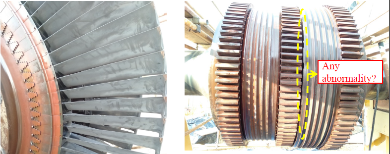
- Any abnormality
Compressor Rotor Blades inspection
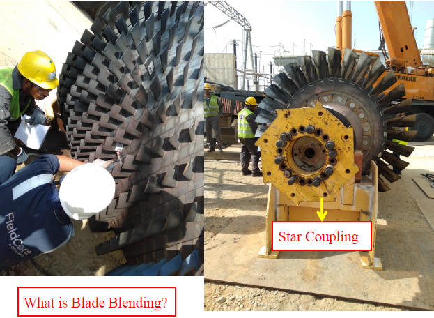
- All the compressor rotor blades are visually inspected. Blades are marked, should any damage, crack and wearing found on blade.
- Blades are then labeled with the row and number. If the blending is required.


