


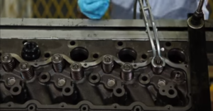
Installing Valve Components into a Cylinder Head
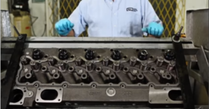
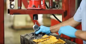
First of all, I would like to recommend you to Always follow your manufacturer’s instructions and remember to use the proper tools for installation. we proceed to install the Cylinder Head valve guide for this step. We need to put a little engine oil on the outside diameter of the valve area. Then with a hydraulic press. We install the Valve guide.

Please check the manufacturer’s manual for the correct Inside diameter.
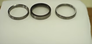
The next step would be to install the valve seats before we start. We need to lower the temperature on the new valve seat so it fits with a proper tool without forcing.

Now we rectified the valve to the correct angle with the valve seat cutter. Please check the manufacturer’s manual for the correct grain. To finalize the installation. We scanned the interior of the valve seats.
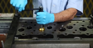
Finally, we proceed to install the other components we take out our spring valves rotor coils lookers and the exhaust in the Inlet valves. Now we assemble valve by Valve. And proceed to install them with our valves spring compressor.
To rectify that we’ve installed our cylinder head valve components correctly. We use a rubber hammer and hit the top softly.
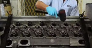
We install the chambers. Now our cylinder head is loaded.
Checking Liner Projection
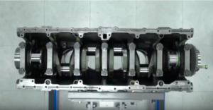
Line your projection is the amount that airliner projects above the Block plane too much or too little line or projection will cause the engines not sealed properly or worse. Break a line or flinch. We begin by inserting the line is dry and without any seals that could prevent the liner from sitting flush on the block for this procedure.

We want to install all six liners inside the block. The gasket is installed.
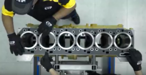
The block plate is largely responsible for the proper liner projection of the engine block plate thickness is equal to the liner flange minus two to six thousands of an inch which is the required liner projection of the engine. The technicians install six special pulldown bolts and washers on the first line are being tested. These boards will hold down the liner and the blocked plates securely so that the liner projection can be accurately checked a linear projection
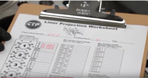
the worksheet is a valuable tool to use during this procedure in it. We will record all the specified measurements for each individual liner.
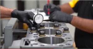
The technician uses a projection checking to hear the dial indicator is measuring for thousands of an inch projection. This is recorded and pulled down bolts are moved over to the third cylinder for measure the liner is checked in four locations around the line. Each measured value is recorded in the liner worksheet. The whole bolts are moved onto the next line.

The technician calculates the values on the worksheet. It ensures that all the parameters for the line of projection on this engine build are within the specified limits. This completes the liner projection procedure.


