


Alternator Theory and Operation
A standard alternator that has a self fully self-contained unit and one thing to remember. When we’re dealing with alternators the essentially what you have is an AC output. But in order to get an AC output. We have to be able to generate some sort of DC current inside to provide a field. That’s done using essentially a DC generator.
We’re looking at a self-contained unit and you can see what we essentially have is the DC generator. And if you recall back to when you took generators. We have a field and we have an armature and it’s that exciter field that provides the Residual magnetism with the north and a south pole.
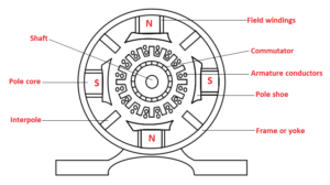
When we turn the exciter armature. Which through the field and you can see exciter armatures. When we turn that exciter armatures through the field using a mechanical force. It’s going to cut across the north and the South Pole. Which in turn will generate a voltage causing current to flow. But the most important part of this particular slide is just to demonstrate that we have a generator. And generator that will, in turn, is going to provide us the current that necessary to produce an AC voltage. If we split this unit in half we could do that and that’s our generator.
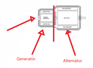
When we go to the other side. We have our alternator and where we’re going to produce our AC output and that’s essentially how a AC is produced on our power lines and that’s what powers buildings and houses.
There are two parts to it but it is one self-contained unit. You will also notice that the prime mover and that prime mover could be a wind turbine it could be a water turbine. We might be using nuclear or coal power to turn this. And when we do that the entire router. This whole thing turns and it does it all at the same time. So clearly you can see that it is a self-contained unit.
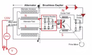
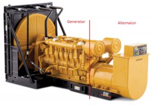 You can see generator part in the images who produces the DC current that we’re going to pass through to our AC Park. So there’s our main AC alternator. We could split this in half and everything on the left side is a generator. And everything on the right side is your Alternator. This gives you an idea of what it actually looks like.
When we start this turning. So first of all just remember your prime mover is turning the entire portion of the rotor and your rotor consists of your alternator field and rotating rectifier. That also includes the exciter rotor. which is the armature of your exciter.
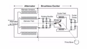
You can see in the picture no load attached at the alternator output. There’s nothing attached. All we’re going to do is look at where current flows once this thing starts turning. Right now at this point, the prime mover is going to bring up the roader part of this machine up to rate its speed. Now there’s only one place for current to flow in this machine with no load attached.
So current starts flow through brushiess exciter and remember this is current because we’re connected to the same two points.

We have an AC first flowing now we come in with AC current to this four-wave bridge rectifier here and of course its job is to convert AC to DC. So we get a rectified DC current now flows out to the exciter field in order for us to start to build up a voltage at our output.
 What had to happen first of all is there had to be residual magnetism due to a small fairly weak north and south pole.
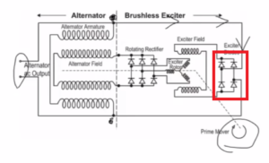
 It should be existing on the exciter field. if there is no residual magnetism. So we’re assuming here that we have some residual magnetism in that north and south pole in the exciter field. which you’ll notice is located in the Stator. This is not a big part of the machine. When you look at the overall alternator it really is just the bell end of it. It doesn’t take up a lot of space because we’re not going to be passing much current through the exciter field as compared to the alternator.
Now exciter field has a low current. But many turns of small wire give us the ability to produce that nice big strong electromagnet to excite our roader.
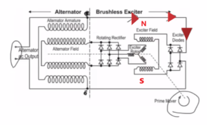
At this point, current is flowing through our exciter diodes creating a bigger north and south pole which of course gives us our lines of force in here.
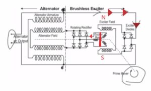 And as this prime mover turns the exciter rotor through those magnetic lines of force that induces an AC voltage onto the exciter rotor. Then AC voltage which is essentially an electrical pressure is going to cause AC current to flow out to our rotating rectifier. Remember this rotating rectifier physically part of the machine it’s built right on the rotor itself.
That AC current goes to our rotating rectifier. Which is rectified by what kind of rectifier. While wouldn’t you know we have a three-phase full wave rectifier. Which will provide a nice or relatively clean DC output which now means that current will flow to our alternator field.
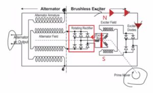
Now unlike the exciter. The alternator field is located on the rotor on the north and south pole for our field are actually part of the rotor that’s turning. Which is the opposite to what we had in the exciter where the exciter field was actually in the stator doesn’t matter where they are.
 The bigger machines are anything over about 1 KVA or a thousand Volt-amps is usually means we have a rotating field in our alternator. we have these magnetic lines of force. That are turning at rated speed cutting across our alternator armature conductors. The alternator armature conductors have a voltage induced in them. Because we have relative motion between a magnetic field and a conductor.
We produce a voltage at our alternator output. The amount of voltage that is produced that our alternator output is dependent upon a few things.
We could look at the number of turns in the alternator armature immature. If we were to increase the number of turns we would increase the amount of induced voltage. If we were to change the armature core in the alternator something that is more permeable would produce a higher output voltage. And the third variable that we can take a look out would be to alter the amount of the strength of the magnetic field in the alternator field.
If I had a stronger north and south pole it was rotating that also would induce a higher voltage in the alternator armature. Realistically the one thing we can control is the strength of the magnetic field in the alternator. So our alternator field is really the only variable that we would realistically control and we can do that through what’s called a voltage regulator. But hopefully, this gives you an idea as to how this operates. Now that we’ve produced our voltage at our alternator output.
And we have not yet connected load we have to talk about a couple of things and that is the voltage drops that occur internally on any machine including in this case and alternator. Now understanding if we go back to our formulas and we look at voltages equal to our current times.
V=iR
Or resistance we know that any time we have 0 current flow that means we have the 0-volt drop. When no current is flowing in this particular case we know that there are no internal Volt drops. There are several Volt drops that occur in an alternator. We have a Volt drop due to the resistance of the actual windings inside. We also have a Volt drop due to our inductive reactance. Inside this machine also have a Volt drop due to armature reaction and that armature reaction is due to the distorted magnetic field.
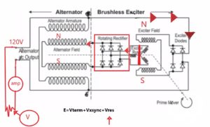
None of these voltage drops happen until we have a load attached and current starts to flow. Just remember whenever we’re talking about alternators and we’re looking at the alternator output. Let’s use an example here and let’s assume that our alternator output is 120 volts AC which is a pretty standard voltage that we use in our houses.
So the idea being is that in order to produce that 120 volts. We had to generate a little bit more than that because we have as soon as we connect the load.
So if we actually connect some load here they’re just showing some sort of a resistance. And then let’s put an amp meter in there to measure current and so we already know then my voltage across the load here that voltage.
We already know it’s going to be 120 neglecting.
You can see in the figure we’ve connected load and current going to flow. Check current is flowing. We are going to have some internal Volt drops so the internal Volt drops. One of them clearly is the voltage dropped across the resistance of all of the armature conductors.
The other one is also voltage xsync.
Now that stands for synchronous reactance. Synchronous reactance is the combination of voltage due to armature reaction. Which is that distortion of the magnetic field and voltage due to inductive reactants. Remember this alternator armature is a coil. Any time we have a coil it has the property of inductance and inductance is the property of an electric circuit that opposes a change in current. So when we take our voltage drop across the inductive reactance and voltage drop due to our immature reaction. And put them together. That combination is called voltage synchronous reactance and that’s represented by X sync.
when we take basically our entire voltage drop due to our in-phase component.
Add to that the voltage drop due to our entire out of phase component. And add to that the terminal voltage. That gives us what we were required to generate in order to get the terminal voltage. So, in this case, let’s just say that our voltage due to resistance drop was 2 volts and our voltage drop due to synchronous reactants was 4 volts.
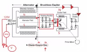
The question is then if I was to maintain a full load. Output at 120 volts assuming that we’re at full load right now with the load we have connected. That would mean that I would have to produce a total of 126 volts. In order for me to have 120 volts on my output. Kerch off voltage law says they have to add up.
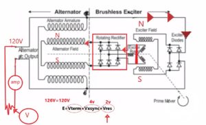
That’s his formula. And when we add up our voltage drops after angle here all of these need to equal 126 volts. So our terminal voltage which is where we connect load is going to be 120 volts.
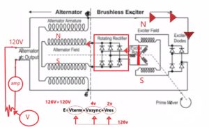
We have 4 volts dropped across the out of phase component. Which is a combination of armature reaction and inductive reactions. And we have two volts drop across the resistance of the windings internally for a total of a total generated voltage of 126 volts.


