


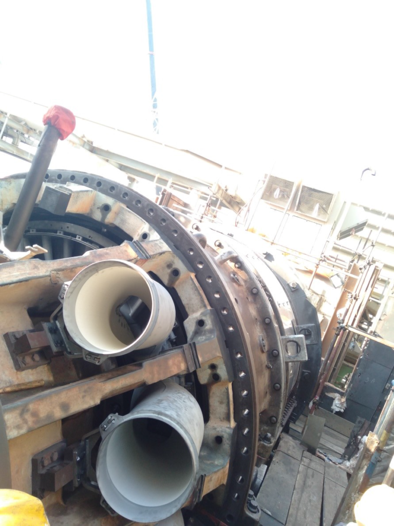
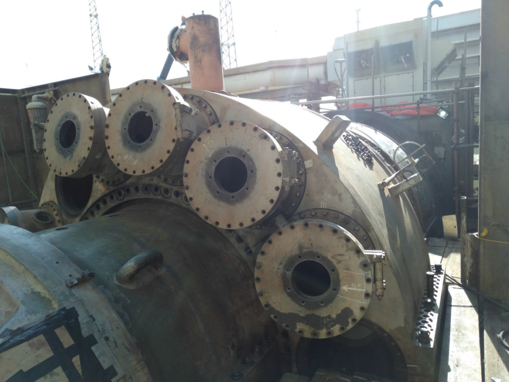
- It is more convenient to install the transition pieces before installing the Combustion wrapper casing. Set back readings are recorded for each of the transition piece. If any reading falls out of the range, should the aft mount bracket bolts be tightened properly.
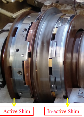
Float and Turbine Clearances Adjustment
Active Shim Thickness= A
In-active Shim Thickness= B
A-Set Reading (actual)= Ca
A-Set Reading (required)= Cr
Note#1: For the adjustment of the float, we play with the thickness of in-active shim without consideration of active shim. For the adjustment of the turbine clearances, we treat both shims and their thickness variation is inversely proportional to each other. The active shim is first to consider while adjusting the turbine clearances.
Float Setting: B ± y (y-thickness variation)
Turbine Clearance Setting: If, A + x; then, B – x
(Ca-Cr = x) or
If, A – x; then, B + x
Note#2: In such cases, where both corrective actions are to be preformed. We can first correct the Float, then, the adjustment of the turbine clearances; or, by combination of both by numerical configuration.
Float and Turbine Clearances Adjustment (Case Study)
Active Shim Thickness= A= 0.562”
In-active Shim Thickness= B= 0.384”
A-Set Reading (actual)= Ca= 10.174”
A-Set Reading (required)= Cr= 10.250”
Float Actual=Fa= 0.026”
- What should be the desired thicknesses of both active and inactive shims in account of float and turbine clearance adjustment?
Float Required=Fr= 0.016”
Alignment
- The alignment is an important exercise to perform in the Major Inspection.
- Pre-Alignment
- The pre-check alignment reading is encountered, from the Turbine to Generator side, for getting a reference value.
- The activity is parallel to CI hardware removal work. The load coupling aft side bolts are first open for alignment reading.
- Post Alignment
- The Post Alignment after positioning the turbine rotor on turbine base.
- This is the final check of the major inspection.
- The alignment is performed from Accessory Base to Turbine and from Turbine to Generator.
Alignment Method: Rim and Face
Alignment Tools: Christmas Tree, Dial Gauge, Slide Parallel, Vernier Caliper, Inside Micrometer


